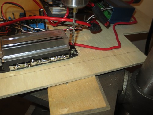
I picked up where I left off last night. First up, Mounting the fuse box, where the positive wires will be attached.
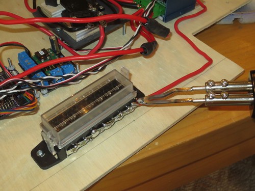
Next, I soldered the main +12 volt wire that comes from the on/off switch to the back side of the fuse box. The tabs for the back side are all soldered together.
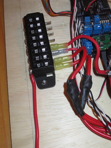
Then, I soldered and crimped connectors onto the 12 volt citizens. The dome drive controller, speed controller (x2) and Stealth power supply all drink from this well.
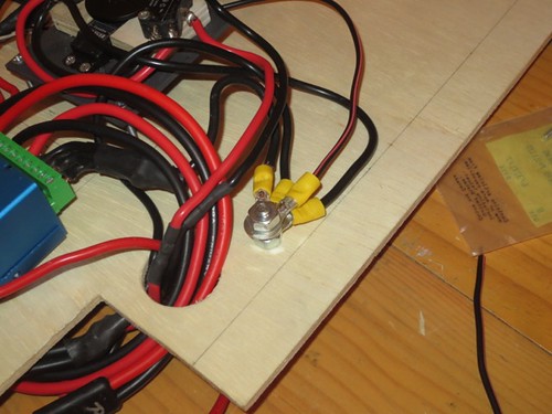
Then, I drilled the hole for the 1/4" bolt that is used for the common negative connection for the 12 volt electronics.

Again, I soldered and crimped connectors (actually, many of these were already on), and screwed them down. I used the continuity tester on my multimeter as I went, and continuity looks good.
And here is the electronics board as it currently sits. I think everything is on there but the VMusic2 and audio.
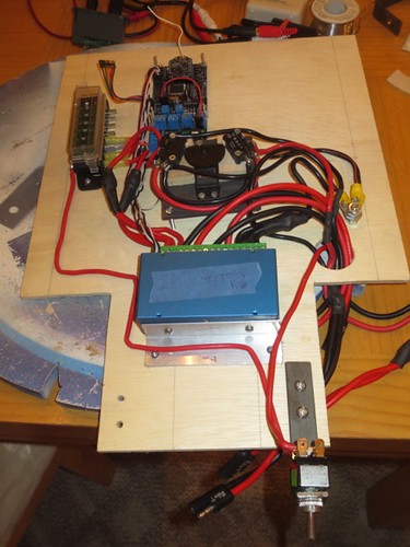
I'm debating about how best to secure the VMusic 2, amplifier and ground loop isolator. At first I was thinking of using Velcro, but I don't think it would suffice. I'm now thinking about opening the cases on the VMusic 2 and the amplifier, and putting screws in the bottom of each case that face down into and through the electronics board, where I'd use a nut to secure them from the back of the board. Not sure if there's enough room in the cases, though. I'll see about this soon.
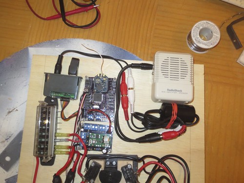
Also, one goof I now see is that the on/off switch on the amplifier will be blocked by the top of the frame when the electronics board sits in the droid. I can always lift the board up an inch to turn it on and off, or maybe mount it slightly higher. If I can figure out a way to power the amplifier's 9 volt DC adapter input, then I can pull the 9 volt battery out, and just leave the dial turned on permanently, and the amplifier will power-up when I throw the main power switch.


