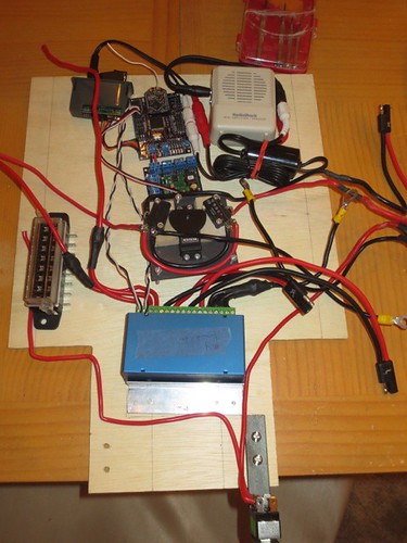
I spent quite a bit of time loosely laying out various configurations, before settling on a placement that I hope will work well.
Time to start drilling. I used various parts as templates for where to drill.
The attachment for the speed controller.
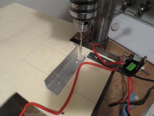
The large hole for connectors to pass through.

Using the dome controller mount plate as a template.
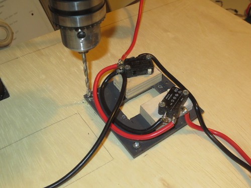
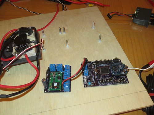
Finally, I used the mounting holes on the Stealth hardware as a guide to mark where to drill, and then drilled the three holes for the DC converter, and the four holes for the Stealth Receiver.
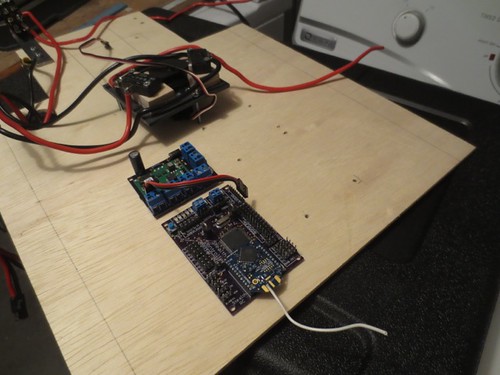
For the Stealth hardware, I'm using #4 screws from underneath, and nylon standoffs and nuts, in order to avoid having metal contact metal. Also, I chose longer screws in case I decide to cover these electronics with plexiglass.
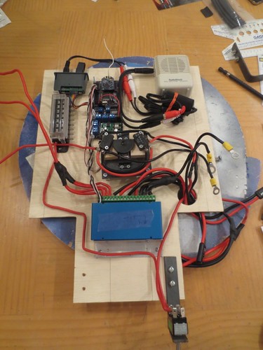
The electronics board, as it currently stands. Loose wires will be cut to size and soldered and/or attached to their mount points, which should help clear up the clutter.
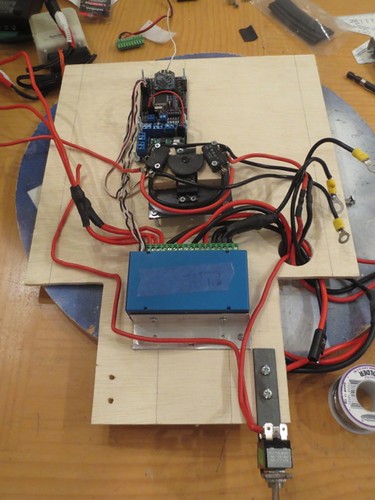
And the electronics board, as I hope to have it in the next day or two.