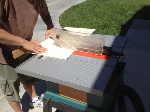
The first step was to cut the correct size rectangle.
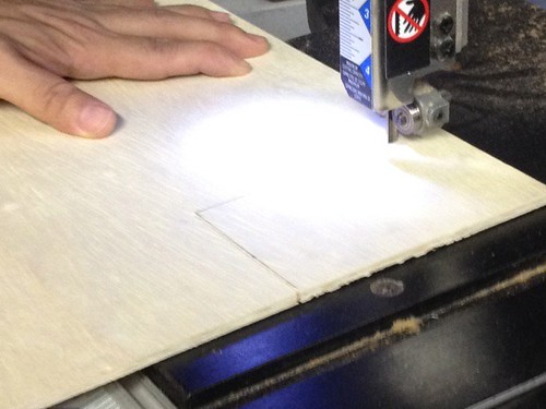
The corners need to be cut from the bottom edge, in order to accommodate the batteries at the bottom of the droid.
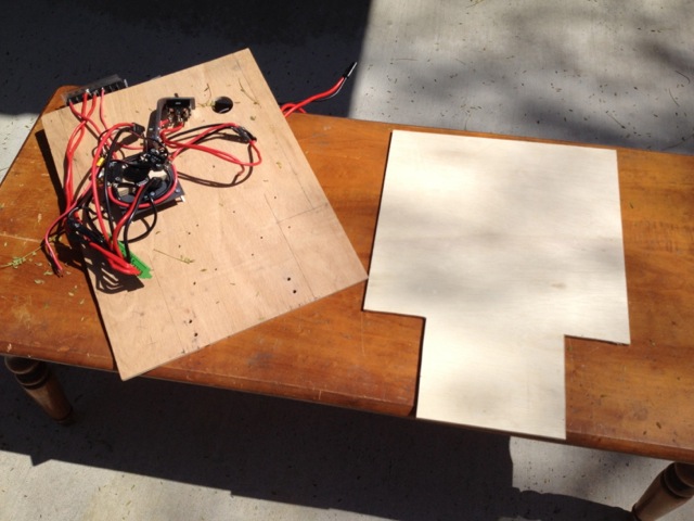
Done. The old board and the new one.
Back home, I did a test fit. Battery clearance looks good at the bottom.
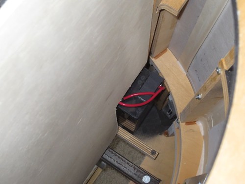
And the fit in the slots in the frame looks good at the top.
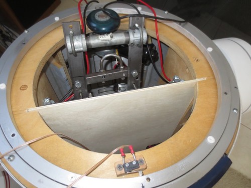
Next up, mounting the electronics.


